E2E hardware-in-the-loop test of an EULYNX TDS
By Niels Geist (TU Berlin).
The aim of this project was to verify the EULYNX conformity of a specific train detection system (TDS) in the form of a Siemens ACM 300 axle counter. The test laboratory required for this was to be equipped with commercially available electronics and should use a maximum of open-source components to implement the verification as a proof of concept (POC).
System environment and existing foundations
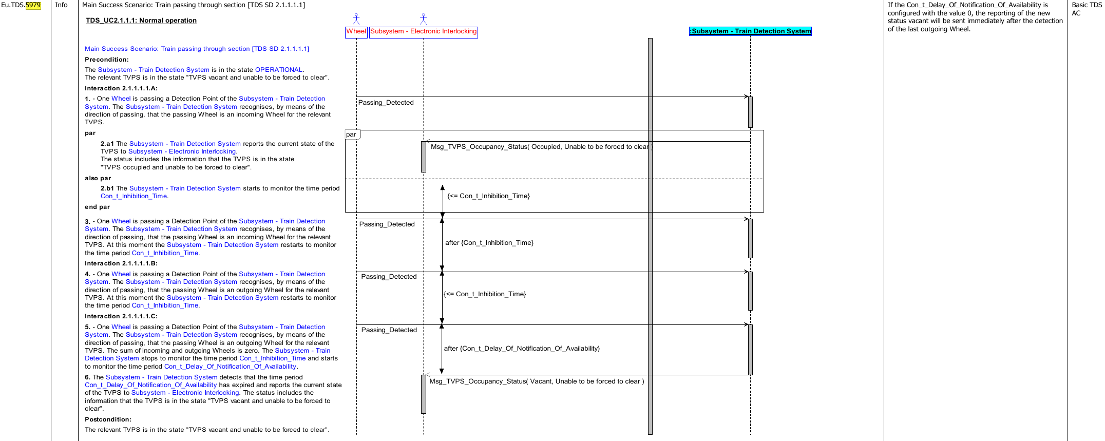
The EULYNX consortium specifies both a test environment that makes all interfaces of the subsystem usable in a laboratory environment and the test cases to be carried out.

Each scenario clearly described by the requirement specifications for subsystems using sequence diagrams is covered by one or more test cases, depending on different preconditions and end states. The expected execution of the test cases can then prove the EULYNX-compliant functioning of a subsystem with regard to the specific scenario.
EULYNX test case format/test cases
The structure of the EULYNX test cases is designed in a way that the test cases can be used to perform E2E hardware-in-the-loop tests on the individual subsystems.
The PARAMETER table lists all the parameters that must be defined before the test case is executed. A parameter can be a variable from the subsystem itself, a timer or a value in a message. These are largely defined by the specific system available.
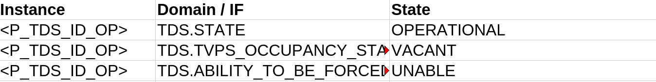
The PRECONDITIONS define the initial state of the subsystem, which must be reproducible by the test laboratory.
The decisive steps for the actual test procedure are the STEPS listed in the table, which describe the exact sequence of the test cases. Each line of the table corresponds to a single action in the test procedure. Unfortunately, these are difficult to translate into instructions that can be executed by our test application.
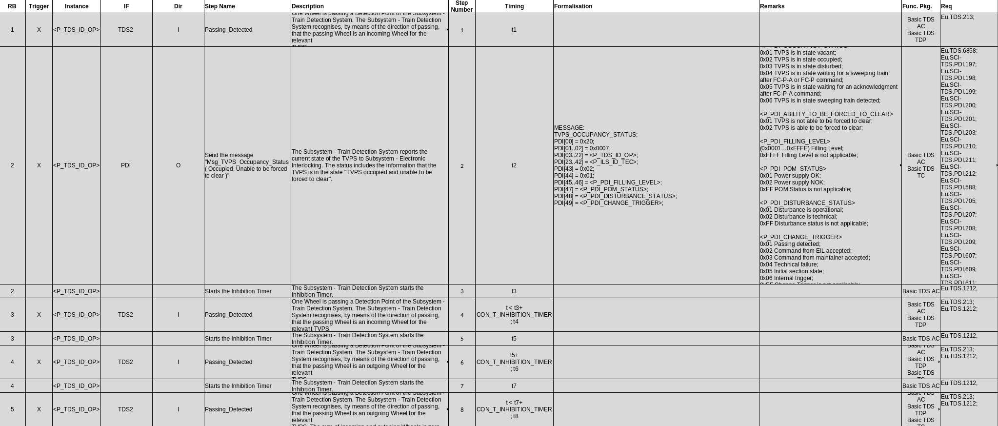
The SDI sheet contains all messages that may occur during the test.
The POST CONDITIONS show the state of the subsystem after the test case has been executed and are easy to compare. Afterwards, either the state for the next PRECONDITIONS or a neutral initial state should be established.

The large number of test cases made it necessary to limit them to the applicable system/functional package (TDS AC - axle counter) and to filter out test cases that could be easily implemented within the scope of this POC.
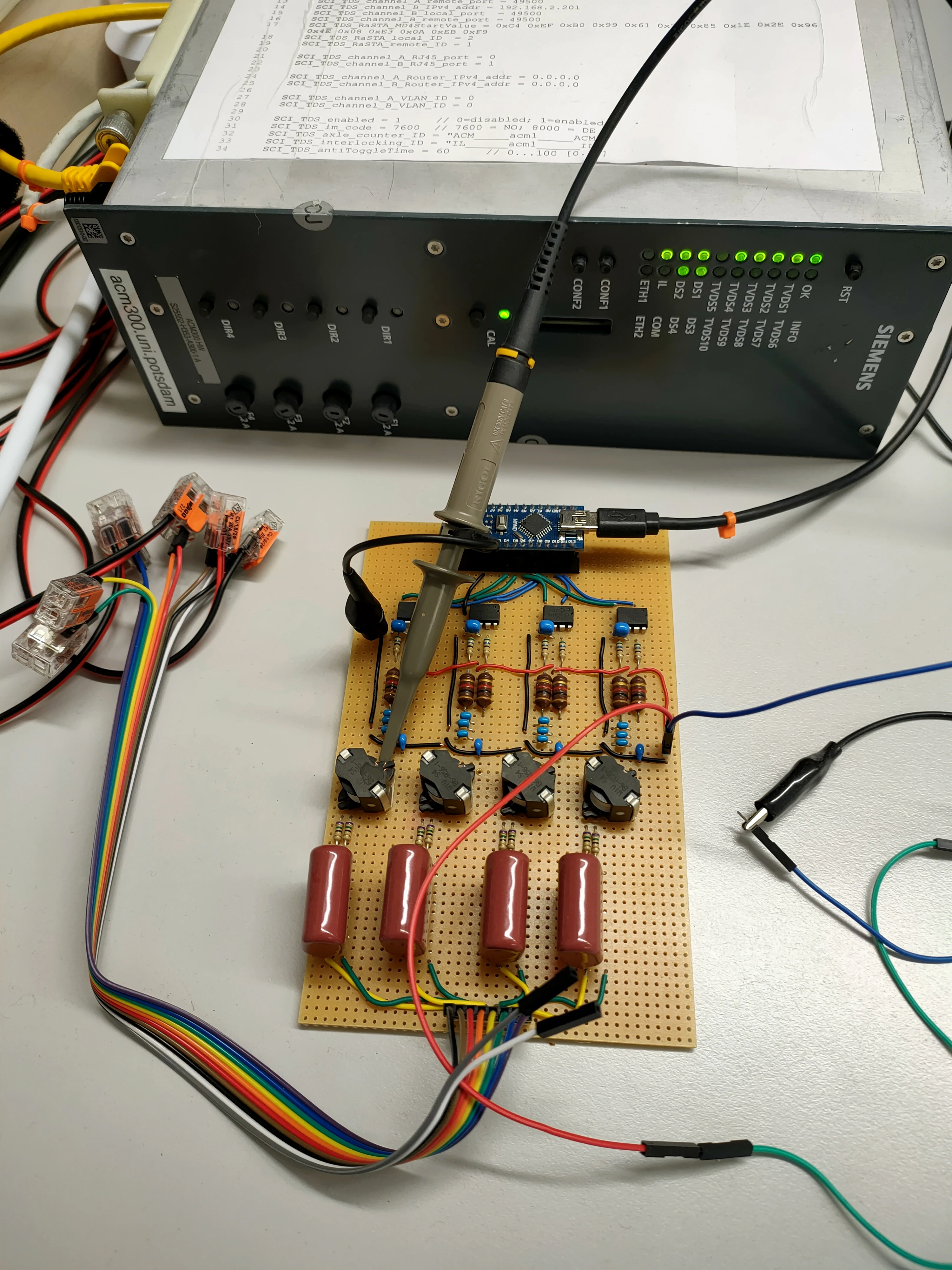
Test/simulation circuit – starting point: laboratory environment
The Digital Rail Summer School project in 2024 had already provided a circuit board with a functioning test setup. Source code was also available that allowed an Arduino to stimulate the coils at the correct frequency. This allowed the axle counter to be set to a correct initial state with unoccupied axle counter heads.
In addition, the Platform 21 provided a tool that was able to establish the necessary RaSTA connection and exchange EULYNX telegrams. Alternatively, it would have been possible to build on the results of EULYNX-Live and derive a minimal interlocking system from it (https://github.com/eulynx-live). A future version of the test runner could also communicate with the platform via gRPC to request the status.
Another important component for verifying the successful execution of the test cases is the OPC UA interface to the axle counter, which makes it possible to read and compare system states that are not transmitted as telegrams.
Implementation
Preparation of the test cases
While pre- and postconditions can be directly adopted as a basis to compare the state, a more comprehensive, partially manual processing is necessary for the steps to make them usable, as can be seen in the following illustration.
"STEPS": [
    {
        "action": "axle_in",
        "confirm": "opcua_axle",
        "expectedValue": 1
    },
    {
        "action":null,
        "confirm": "grpc",
        "expectedValue": {
            "TDS.STATE": "OPERATIONAL",
            "TDS.TVPS_OCCUPANCY_STATUS" : "OCCUPIED",
            "TDS.ABILITY_TO_BE_FORCED_TO_CLEAR" : "UNABLE"
        },
        "wait": 0
    },
    {
        "action":null,
        "confirm": "opcua_timer",
        "expectedValue": 1500
    },
    {
        "action": "axle_in",
        "confirm": "opcua_axle",
        "expectedValue": 2
    },
    {
        "action":null,
        "confirm": "opcua_timer",
        "expectedValue": 1500
    },
    {
        "action": "axle_out",
        "confirm": "opcua_axle",
        "expectedValue": 1
    },
    {
        "action":null,
        "confirm": "opcua_timer",
        "expectedValue": 1500
    },
    {
        "action": "axle_out",
        "confirm": "opcua_axle",
        "expectedValue": 0
    },
    {
        "action":null,
        "confirm": "opcua_timer",
        "expectedValue": 1500
    }
]
Software and platform
A script implemented in Python coordinates all the important steps as a test runner to automatically run the test cases one after the other. The precondition for this is the establishment of a functional connection between the interlocking, which is simulated by Platform 21, and the axle counter. The test case JSON specifies the test runner for the axle sequence, which is transmitted to the Arduino via the serial interface. The Arduino interrupts the stimulation of the two coils one after the other for the duration of a passing axle to simulate its passing and direction of movement. The reactions of the axle counter are received by Platform 21 in the form of EULYNX telegrams and then queried by the test runner. If the test step expects a telegram to be sent, this is compared with the test definition. At the same time, the expected state is compared via OPC UA in the AC. This means that each test step can be checked for correctness independently of communication with the simulated interlocking. The complete correctness of a test case therefore results from the conjunction of the individual steps and the Boolean values can be seen as the basis for a readable test report.

Demo
Next steps
After successful implementation of the POC, it was possible to show that it is possible to set up a EULYNX laboratory for an axle counter that can prove the conformity of a specific device type with the EULYNX specifications. The following steps for transferring the laboratory to a state approximating production maturity are conceivable.
All test cases must be converted into the format described above and executable by the test runner. It makes sense to continue to rely on the highest possible level of automated creation in order to exclude human error during the transfer.
The reliable (re)creation of the initial state and the preconditions of the next test case should also be the subject of more detailed investigations. In particular, it is necessary to evaluate whether a neutral intermediate state is necessary or whether it is possible to proceed directly to the preconditions of the next test case.
The influence of the track topology and the design of the Train Vacancy Proving Sections (TVPS) on the execution of the test cases was not investigated in detail, since the stored topology in different TVPS can lead to different results (e.g. leaving one section means entering another section, as different test cases). This raises the question, whether the TVPS should be tested one after the other and how the state of neighboring sections can be kept free of interference and also restored to a suitable initial state.
In addition, suitable reporting formats for documentation must be defined and integrated before the laboratory’s capabilities can be expanded to include axle counters of a different design, other TDS and further field elements.
Sources
- EULYNX Requirements specification for subsystem TDS Eu.Doc.43 v4.2
- EULYNX Testcases TDS, in particular
- TDS_UC2.1.1.1 Normal operation_Eu.TDS.5979_TC_Eu.TDS.5979.01
- TDS_UC2.1.1.2 Incorrect counting/Eu.TDS.5981/TC_Eu.TDS.5981.02
- EULYNX Format specification for EULYNX Certification test cases v1A